| |
|
|
|
 |
|
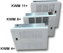
KICKSTER™ WM+ Series Hydronic Fan Coils
KICKSTER™
WM+ Series 3K to 11K Hydronic Fan Coils Model KW4 4+, KWM 6+,
and KWM 11+ Wall mount units. All units can be rotated
vertically up or down.
|
|
Introducing
the new KICKSTER™ WM+ series hydronic
wall mount fan coils. Another brilliant innovation from
Turbonics, Inc. A leading manufacturer of hydronic fan coils in the United States.
The new
"K" series of Wall Mount hydronic Fan Coils are
completely "Konstruction Ready". Wall Mount units
are vertically rotatable allowing either top or bottom piping
and wiring connections for contractor friendly install.
|
DOWNLOAD
Installation & Application Manual |
|
KICKSTER™
WM+ FAN COILS, BASED ON CAPACITY ARE THE MOST COMPACT AND
RELIABLE WALL MOUNTED HYDRONIC FAN COILS IN THE BUSINESS. THEY
CAN BE USED WITH HEATED POTABLE WATER OR OTHER GLYCOL/WATER
FLUIDS. THEY CAN BE CONNECTED TO VARIOUS TYPES OF WATER
HEATERS OR BOILERS UTILIZING VIRTUALLY ANY SOURCE OF ENERGY
FROM NATURAL GAS, PROPANE OR OIL TO SOLAR, GEOTHERMAL OR WASTE
HEAT FROM PROCESS.
*
Stud mount brackets can be moved up or rotated for “on
drywall” installations
** Units are shipped to be installed with pipes from above. If
piping from below ask for a DD ddddd(Double
Down) cover.
*** Units can be slipped into drywall finished walls as long
as “Flexible Connector Kits” are used.
STANDARD
SPECIAL FEATURES
-
KWM’s
fit between studs and are to be installed before drywall.*
-
KWM’s
can be mounted in either a piping from below or above
configuration.**
-
KWM’s
have switches that can be rotated depending on mounting
orientation and depth of drywall.
-
KWM’s
have pipes that extend beyond the shell of the unit for
easy installation of piping.***
-
KWM’s
have their cover’s wrapped separately for quick trim
installation after drywall finish.
-
KWM’s
come with a pre-construction internal “Debris Cover”
removed just before cover installation.
-
KWM’s
use “4 corner internal mounting” to provide a closer
wall fit against variations in drywall finish.
-
KWM;s
follow the basic and traditional thermodynamic rules of
“circular” airflow patterns.
-
KWM’s
use the tried and true Propeller Fan Technology which has
become a cornerstone of Turbonics.
-
KWM’s
use high output heater cores designed to extract the
maximum amount of energy possible
-
KWM’s
heater cores output capacity is verified by ISO 9000
certified factory in business for 50 years.
-
KWM’s
4+ and 6+ cores use a standard 6 or 8-pass serpentine flow
5/8" copper and have 6 fins per inch.
-
KWM’s
11+ heater cores use 18-pass 3/8" copper connected to
5/8" manifolds and have 8 fins per inch.
- KWM’s
use proven components and operating characteristics of fan
coils used for over 15 years.
|
SHORT CIRCUITED AIR FLOW
SYNDROME
Unit Output
Capacity and the effectiveness of the units ability to provide comfort in a room
are dependent on several factors. Design, construction, core ratings, air
flow, air velocity, fluid flow rate, supply temperature of fluid and the
temperature of the entering air all play a major role in determining whether an
occupant of a room will experience perfect human thermal comfort. Of course it
is important that a unit is properly sized to adequately satisfy the calculated
heat load and it is generally assumed that this has been done by professionals.
Professional HVAC
designers try to create a circular airflow to touch the farthest point of the
room, preventing drafts and “layering” that can cause discomfort. Furniture
that is placed in front of a fan coil unit will restrict air flow, causing
occupants to move furniture if necessary. But what happens when just plain poor
product design allows air from the supply outlet to short circuit or flow into
the supply inlet of a fan coil device?
|
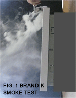 Actual
output capacity can be reduced by as much as 15 to 25% or more depending on the
room that is being heated. As in Fig. 1 poor product design allows air from the
supply to be drawn back into the units air intake. The cause for this is
insufficient air velocity and poor louver design. The result is a further
reduction in velocity which defeats the units ability to throw heat into the
room and a significant reduction in rated capacity as inlet air is “pre-heated”.
Heated air basically sits in front of the unit and the room is not adequately
heated to proper comfort levels. Actual
output capacity can be reduced by as much as 15 to 25% or more depending on the
room that is being heated. As in Fig. 1 poor product design allows air from the
supply to be drawn back into the units air intake. The cause for this is
insufficient air velocity and poor louver design. The result is a further
reduction in velocity which defeats the units ability to throw heat into the
room and a significant reduction in rated capacity as inlet air is “pre-heated”.
Heated air basically sits in front of the unit and the room is not adequately
heated to proper comfort levels.
|
|
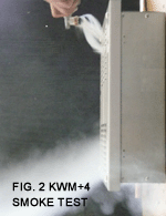 As
in Fig. 2 excellent product design ensures proper air velocity and good louver
design prevents the short circuit of supply air into the air inlet. The result
is more heated air is distributed into the room while the unit operates at full
rated capacity. So by properly positioning your furniture and by using great
products with proper design, perfect human thermal comfort can easily be
achieved. As
in Fig. 2 excellent product design ensures proper air velocity and good louver
design prevents the short circuit of supply air into the air inlet. The result
is more heated air is distributed into the room while the unit operates at full
rated capacity. So by properly positioning your furniture and by using great
products with proper design, perfect human thermal comfort can easily be
achieved.
|
Contact Turbonics Inc.
When it comes to heat,TURBONICS has been providing it for 30years! Turbonics Inc., Specialists in Hydronic Heating Solutions for Residential, Commercial and Industrial applications.
Turbonics, Inc. PH: (216) 741-8300 www.turbonicsinc.com
|
|