|
I am starting a series on Circuitry and Troubleshooting. It is designed to assist the heating technician in diagnosing and troubleshooting electrical circuits used on heating systems. It is specifically targeted toward gas heating systems. It should however be noted that many of the techniques used herein can be applied to troubleshooting any type heating system.
It is not the purpose to teach basic electricity but some basics are necessary in the beginning. It is our approach that practical application to actual troubleshooting is what is needed. This article will give some insight to electrical or electron theory but is only to give some electrical fundamentals. That is not to say that any knowledge of electricity will not help you it most certainly will.
THIS SERIES IS FOR YOU
IF:
· You have trouble knowing where to start in a circuit diagnosis.
· You are intimidated by circuitry
· You spend a lot of time troubleshooting heating systems.
· You find that you have a lot of callbacks.
In the first few articles we will include some definitions and some electrical theory – or better electrical relationships. There is also a section on circuit components and symbols used in wiring diagrams. There will be a section on circuits and diagrams. We will also go over test equipment and meters.
APPLIED ELECTRICITY FOR GAS APPLIANCE SERVICEMEN
Everything on this earth is made up from tiny particles, so small they cannot be seen with the most powerful microscope. These particles are attracted to each other with great force in the case of solid materials like iron or copper, with less force in the case of liquids like water or oil, and with the least force in the case of gases like oxygen or hydrogen.
Scientists have identified several different kinds of these particles, but the only one that holds our interest when learning about electricity is the electron. Electrons exist everywhere -- in the air, water, in every single object in the world.
During normal conditions, each object on the earth has its own definite number of electrons. The number depends upon the size and nature of the object. In metals like copper, silver, or aluminum, some of the electrons are continually wandering around inside the metal itself. These electrons are known as "free electrons", because they are free to move. The rest of the electrons always stay in the same locations; in fact, if we could move them, we would be able to change one metal to another. We could then make gold out of lead. Whenever an object has its normal number of free electrons, that object has no electricity and is said to be "neutral" or "uncharged". We can secure electricity either by taking some of these free electrons away from an object or by adding more free electrons to an object, because we then upset the normal
balanced condition. It can be said then, whenever an object has more or fewer electrons than normal, electricity exists in an object. An example of this is an automobile, which will collect free electrons from dust particles in the air as it is being driven. When the automobile is stopped and a person standing on the ground touches the automobile, the extra free electrons rush to the earth to neutralize the automobile and a slight shock may be felt if enough current passes through the body.
But where can we get extra free electrons? We get free electrons in our work from a battery, a power line, a thermocouple, or a thermopile. So that we can understand the movement of electrons, which would be an electric current, let us examine the law of electric charges. There are two kinds of charges, quite unlike, and for convenience they are called "positive charges" and "negative charges”. An object or terminal that has a “negative charge” contains more electrons than normal. An object or terminal has a “positive charge” when ever it has fewer electrons than normal.
Two electric charges cannot exist side by side without trying to move each other. Nature has its own law, which tells which way they will move. If two charges are alike (both positive or both negative) they will repel each other or tend to push each other away. If the two charges are unlike (one positive and one negative) they will attract each other and tend to move together. Lets repeat this law. Like charges repel. Unlike charges attract.
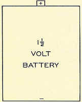
FIGURE 1
Let us apply this to a flashlight battery (Fig. 1). A battery always has two terminals, one having more electrons than normal and the other having less electrons than normal. The battery itself produces this condition by chemical action, which need not be studied here.
The battery terminal, which has more electrons than normal, is called the “negative terminal” (An electron is a negative charge). We use a minus (-) sign to indicate that this terminal is negative.
The battery terminal, which has fewer electrons than normal, is called the positive (+) terminal.
The electrons on the negative terminal want to go to the positive terminal of their own battery.
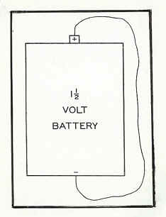
FIGURE 2
When we connect a wire between the two terminals of the battery, we secure a "complete circuit" (Fig. 2). Here is what happens: The instant the circuit is completed, the extra electrons on the negative terminal rush into the wire because they "sense" a clear path ahead to the (+) terminal. These moving electrons from the battery bump into free electrons in the wire, and push the free electrons forward toward the positive terminal. In no time at all, every electron gets bumped. All along the wire, electrons begin pushing other electrons toward the (+) terminal. Each time an electron is pushed into the (+) terminal, another electron enters the wire from the (-) terminal.
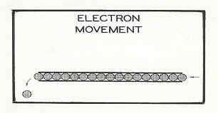
FIGURE 3
The movement of electrons through a complete circuit can be compared to the movement of marbles through a length of tubing (Fig. 3). Each time a marble is pushed in one end of the tubing, an entirely different marble pops out of the other end of the tube.
The movement of electrons through a complete circuit is called an electric current. The more electrons we have moving past a given point in the wire each, second, the greater is the value of current flowing through the wire.
Reviewing the behavior of current through a wire we realize that when one end of a wire is connected to one terminal of our 1-1/2 volt battery, the free electrons in the wire are ready to “go places” but nothing can happen yet. Our wire is merely an extension of the terminal it is connected to. When we connect the other end of the wire to the remaining terminal of the battery, we get action immediately because the circuit is completed.
CONDUCTORS
Conductors have many free electrons. These electrons are easily pushed around; therefore, it is easy to pass current through a conductor. Most metals are good conductors of electricity (Fig. 4). Copper is generally used because of its abundant supply, thus being more economical. Copper offers very little resistance to electron flow, and when used as short pieces of connecting wire, such as in an appliance, the resistance is considered to be zero.
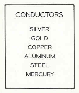
FIGURE 4
CONDUCTOR SIZE
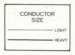
FIGURE 5
The size of the wire is important when designing the electrical section of an appliance. Wire size is determined by the amount of electricity that must be supplied to a current-using device. For instance, a thin copper wire will relay a few electrons easily; however, if the electrons are pushed too fast, they resist this fast movement in the form of friction.
This friction produces heat and could possibly melt the wire. This is called overloading (Fig. 5). Heavy copper wire has many more free electrons than the small copper wire. This means that many electrons may be relayed along the wire to do heavy work without having to travel so fast, thus avoiding overloading.
INSULATORS
Insulators have very few free electrons and these free electrons cannot be pushed from one section of the insulative material to another section. Since these materials will not allow their electrons to be relayed, they will not pass an electrical current (Fig. 6). By covering conductors with insulative material, the current must follow through the conductor and perform the work it was intended to do. The type of insulative material chosen should depend upon the conditions of installation. Plastic material is a good insulator where heat is not involved. High temperature insulation is preferred where the surrounding temperature is high.
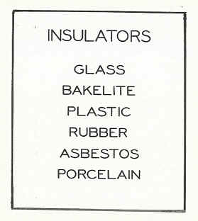
FIGURE 6

FIGURE 7
RESISTORS
Resistive materials have a few free electrons but not an abundant supply like conductors. These electrons can be pushed if sufficient force acts against them. When they are moved, the friction caused by resistance produces heat (Fig. 7). Further, the resistance of the material increases with heat. This is fortunate because we can use the increased resistance of heat to regulate the flow of current through a current-using part. For instance, we want the filament of an electric light bulb to get to a white heat to emit light, but not hot enough to melt. The manufacturer of the bulb carefully selects the type of filament material, the cross sectional size, and length to produce the amount of light desired without burning up. As the filament gets to a white heat, the increased resistance of the material limits the flow of current through the filament.
ELECTRICAL MEASUREMENTS
The following electrical measurements are compared to gas for ease of
understanding. Although this cannot be done with complete accuracy, the similarities will help to understand electrical measurements. Let us review for a moment how natural gas accomplishes its work. First, we need a quantity of gas. Second, we need pressure to force the gas to a burner so that the ultimate power can be realized. The amount of power developed depends upon how many B.T.U.’s are consumed during a certain time, normally expressed in "B.T.U. 's per hour". If the pressure remains constant we can increase the power by increasing the B.T.U. content of the gas. Or, if the B.T.U. content remains constant, increasing the pressure can increase the power. A third consideration is the resistance in the transmission lines, which reduces the pressure along the line. In fact, an orifice is used at a burner to limit the flow of gas to only that quantity desired for the burner.
Voltage
The electrical “pressure” which is capable of setting electrons in motion in a circuit is called “voltage” (Fig. 8). The stronger the voltage the greater the effect it has on electrons. Like gas pressure, voltage is the force that moves the electrons along a wire in a circuit. Voltage is sometimes referred to as the electromotive force (E.M.F.). A volt is a unit of electrical pressure.
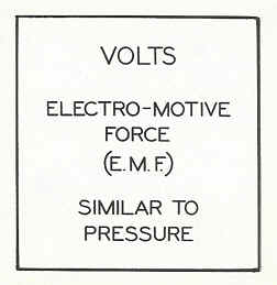
FIGURE 8
Amperes
The electron movement produced by voltage is called “current”. The more electrons we have moving past a given point per second, the stronger the current will be (Fig. 9). The basic unit for specifying the strength of a current is called the "ampere”. We, therefore, compare amperes to a cubic foot of gas because it is the amount of fuel available. If we increase the voltage in a circuit, we increase the strength of the current. Like gas, if we increase the pressure, the amount of gas passing a given point in a given length of time is also increased.
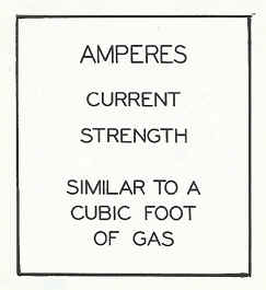
FIGURE 9
Ohms
The opposition to voltage is called "resistance” (Fig. 10). The resistance of a current-using device determines the amount of current that will be used. We can compare "ohms" to a limiting orifice of a gas burner. The orifice size determines the amount of gas that a burner will consume.
FIGURE 10
We have a two NEW book just in their first printing. The first one is titled FUNDAMENTALS OF GAS VOLUME I it will be priced at $75.00 a copy + $10.00 shipping and handling. In addition we have just finished FUNDAMENTALS OF GAS Volume II, which covers “Air for Combustion” and “Venting” it is up to date with the latest changes to the Fuel Gas Code Book. It is also being offered at a price of $75.00 + $10.00 shipping and handling.
The seminar schedule for training at the Gas Training Institute can be found in the HVAC Insider Bulletin Board. The seminars cover:
· Fundamentals of Gas
· Circuitry and Troubleshooting
· Basic Electricity
· Venting
· Hydronic Controls
· Electric Ignition Systems
· Advanced Electric Ignition Systems
· Conversion Burners/Combustion Testing
· Powerpile Systems
If you are interested in information call 401-437-0557 or write to:
Gas Appliance Service Training and Consulting
22 Griffith Drive
Riverside, RI 02915
E-mail gastc@cox.net
###
|