|
This is a continuation of the series on Circuitry and Troubleshooting.
It is designed to assist the heating technician in diagnosing and troubleshooting electrical circuits used on heating systems. It is specifically targeted toward gas heating systems. It should however be noted that many of the techniques used herein can be applied to troubleshooting any type heating system.
It is not the purpose to teach basic electricity but some basics are necessary in the beginning. It is our approach that practical application to actual troubleshooting is what is needed. This article will give some insight to electrical or electron theory but is only to give some electrical fundamentals. That is not to say that any knowledge of electricity will not help you it most certainly will.
THIS SERIES IS FOR YOU
IF:
· You have trouble knowing where to start in a circuit diagnosis.
· You are intimidated by circuitry
· You spend a lot of time troubleshooting heating systems.
· You find that you have a lot of callbacks.
In the first few articles we will include some definitions and some electrical theory – or better electrical relationships. There is also a section on circuit components and symbols used in wiring diagrams. There will be a section on circuits and diagrams. We will also go over test equipment and meters.
Watts
Watts is the amount of power consumed by an electricity-using part (Fig. 11). Watts are computed by multiplying the voltage drop through a part by the amperes. A single watt is similar to a single B.T.U. In gas, as we all know, we express the hourly rating of a gas burner by B.T.U. per hour. Like B.T.U.'s, watts mean nothing to us unless consumption per unit of time is included. An electricity-consuming device is rated according to the number of watts used in an hour, and is referred to as a watt-hour. Watts then are comparable to the B.T.U. per hour rating of gas appliances. For instance, a sixty-watt bulb means that 60 watts will be used in one hour by the bulb. An electric company bills its consumers by a unit consisting of 1000 watts (one kilowatt). Similarly, a gas company bills their customers by the 100 cubic foot unit. A watt equals 3.415 BTU's. It is often spoken of when discussing transformer power as the “VA” rating of the transformer such as a 40 VA transformer. In this instance VA stands for “Watts”, 40 VA being 40 Watts.
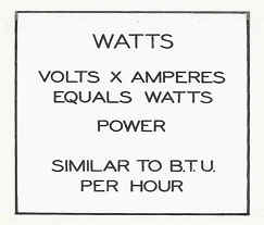
FIGURE 11
HOW ELECTRICITY IS PRODUCED
Electricity is produced in four principal ways (Fig. 12):
(1) Chemically, by means of dry cells or storage batteries.
(2) Mechanically, by means of generators.
(3) Thermally, by means of the thermo- couple.
(4) Statically, which is nature's way of causing an object to become unbalanced in its number of electrons thus leaving the object charged. An example of this type of electricity is lightning caused by a cloud being unbalanced, and when electrons jump between the cloud and the earth in an effort to become balanced, the “spark gap” or “lightning" is the result.

FIGURE 12
TYPES OF ELECTRICITY
There are two types of electricity used in gas appliances.
Direct Current
The first of these is Direct Current, abbreviated D.C. (Fig. 13). Direct current means that the electrons travel in one direction only through a circuit. A flashlight battery produces D.C., and if we connect a flashlight battery to a meter, the polarity and amount of current will be measured (Fig. 14).
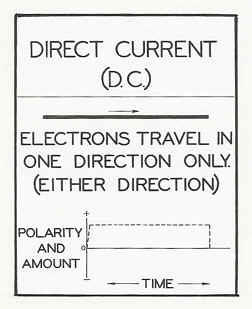
FIGURE 13

FIGURE 14 FIGURE 15
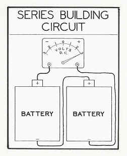
FIGURE 16
Reversing the current in the wire by interchanging the ends of the wire to the battery reverses polarity of current through the wire, but the amount of current is not changed (Fig. 15) Direct Current then does not denote the direction of electron travel in the wire, but does tell us that the movement of the electrons in the wire is always in one direction.
Batteries can be connected in series with the positive and negative poles connected together in order to add the voltage. This is called “series building circuit” (Fig. 16). Each battery can be compared to a small compressor, and if two compressors are connected in series, the voltage or pressure will be doubled. Two batteries then can be compared to a two-stage compressor. As many batteries as needed could be added in a series building circuit to gain the voltage of Direct Current desired.
Batteries connected in a "series bucking circuit” means that negative terminals are connected together, and the positive terminals are connected together (Fig. 17) In this case each battery attempts to push electrons into each end of the wire with exactly the same pressure. Since equal forces act against both sides of the electrons, there is no movement, so there is no current. It is important to remember the possibility of producing series building or series bucking circuits when using the Millivolt Circuit Tester. For instance, when using this tester at the thermostat of a furnace, the pilot should be turned off and allowed to become cool so that the voltage from the pilot generator and the tester cannot produce a series building or a series bucking voltage.
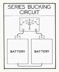
FIGURE 17
A thermocouple also produces direct current (Fig. 18). Since the metal of the thermocouple heats and cools slowly, the production of electricity takes time to build up when the pilot is first lighted or reduce when the pilot is extinguished Thermocouples connected in series add their voltage to produce a stronger current.
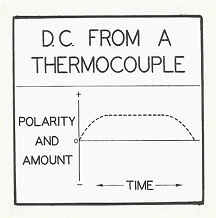
FIGURE 18
We just finished our latest manuals Circuitry and Troubleshooting Volume I and Volume II. They are selling for $75.00 for Volume I and $35.00 for Volume II + $10.00 shipping and handling.
We have a two NEW manuals in their second printing. The first one is titled FUNDAMENTALS OF GAS VOLUME I it is priced at $75.00 a copy + $10.00 shipping and handling. In addition we also have FUNDAMENTALS OF GAS Volume II, which covers “Air for Combustion” and “Venting” it is up to date with the latest changes to the Fuel Gas Code Book. It is also being offered at a price of $75.00 + $10.00 shipping and handling.
The seminar schedule for training at the Gas Training Institute can be found in the HVAC Insider Bulletin Board. The seminars cover:
· Fundamentals of Gas
· Circuitry and Troubleshooting
· Basic Electricity
· Venting
· Hydronic Controls
· Electric Ignition Systems
· Advanced Electric Ignition Systems
· Conversion Burners/Combustion Testing
· Powerpile Systems
If you are interested in information call 401-437-0557 or write to:
Gas Appliance Service Training and Consulting
22 Griffith Drive
Riverside, RI 02915
E-mail gastc@cox.net
CIRCUITRY AND TROUBLESHOOTING
(Part Three)
This is a continuation of the series on Circuitry and Troubleshooting.
It is designed to assist the heating technician in diagnosing and troubleshooting electrical circuits used on heating systems. It is specifically targeted toward gas heating systems. It should however be noted that many of the techniques used herein can be applied to troubleshooting any type heating system.
It is not the purpose to teach basic electricity but some basics are necessary in the beginning. It is our approach that practical application to actual troubleshooting is what is needed. This article will give some insight to electrical or electron theory but is only to give some electrical fundamentals. That is not to say that any knowledge of electricity will not help you it most certainly will.
THIS SERIES IS FOR YOU
IF:
· You have trouble knowing where to start in a circuit diagnosis.
· You are intimidated by circuitry
· You spend a lot of time troubleshooting heating systems.
· You find that you have a lot of callbacks.
In the first few articles we will include some definitions and some electrical theory – or better electrical relationships. There is also a section on circuit components and symbols used in wiring diagrams. There will be a section on circuits and diagrams. We will also go over test equipment and meters.
Alternating Current
Alternating Current, abbreviated A.C., is the type of current that is supplied to homes by the Electric Utilities.
Let us see how a generator produces alternating current. We need three things to produce electricity from a generator: (1) A magnetic field, (2) A loops of wire, and (3) Motion between the two.
If a sheet of cardboard is placed over a bar magnet, and iron filings are sprinkled evenly over the cardboard, the iron filings will arrange themselves in definite lines. This proves to us that invisible magnetic lines of force (Fig. 19) exist around a magnet. When the magnet is bent in a U shape (Fig. 20) the lines of force are concentrated between the ends. The ends are generally referred to as the poles.
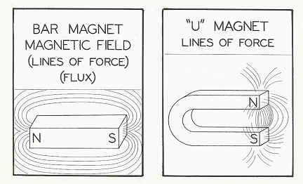
FIGURE 19 FIGURE 20
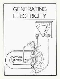
FIGURE 21
When a wire loop is moved so that it cuts through the lines of force, electrons are forced to move through the wire loop in one direction, thus producing a current in the wire (Fig. 21). If the loop is moved across the magnetic lines of force in the opposite direction, the electrons will reverse their direction of travel resulting in a current in the opposite direction through the wire loop. The strength of the current can be in- creased by (1) increasing the magnetic lines of force, (2) adding more loops to the wire, or (3) increasing the speed at which the loops cut the lines of force.
There are laws that tell us which direction the electrons will move, but this has no value for us in our study of electricity so it will not be explained. The important thing to remember about A.C. is that the current continuously reverses its direction in the wire.
As explained before, when the loop passes through the magnetic lines of force, a current is established in the wire loop in one direction. When the direction of movement of the loop is reversed, a current is established in the wire in the opposite direction (Fig. 22). This is termed one cycle of generation. Notice that first a positive current is generated and in the last half of the cycle a negative current is generated. Also notice that at two instances in one cycle the amount of current is zero.
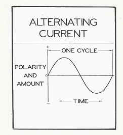
FIGURE 22
When a generator is constructed so that the current changes from positive to negative 60 times in one second, the electricity produced is termed 60 cycles A.C. The generator shown in Figure 22A shows the basic construction of a generator used for supplying house current. Two sets of windings are used to provide three sources of alternating current. These windings are wound around the ends of a C-shaped piece of iron. A magnet fixed to an axle is turned by external power, so that the magnetic field from the magnet cuts across the windings. The C-shaped iron merely concentrates the magnetic field, thereby increasing the efficiency of the generator.
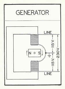
FIGURE 22A
First let us study the top winding of this generator. One end of this winding is grounded to earth. The other end is insulated and will be a "hot wire". When the magnet is turning and in the position as shown in Figure 22A, the magnetic field is parallel to the top winding so lines of force are not cutting the coil. In this position, the generator is not producing a current. As the magnet turns, the lines of force start cutting the winding on an angle, so the generator starts generating a current. (We will assume that this generator is constructed so that when the North Pole of the magnet cuts across a coil, it will produce a positive current.) When the magnet is turned one-quarter of a turn from the position as shown, maximum lines of force are cutting the top coil so the generator is producing its maximum voltage of positive polarity. As the magnet continues to turn, the voltage reduces, and when one-half turn has been completed, the current generated in the top coil will again be zero. At this time the South Pole of the magnet is approaching the top winding, which means that the lines of force are now running in the opposite direction. As the magnet turns through the last half of one revolution, the voltage will go from zero to maximum voltage of negative polarity and again return to zero. When the magnet has completed a full turn, one cycle will have been completed, and the current generated in the top wire will appear as in Figure 22. Notice that the current first went positive, reached a maximum, and then returned to zero. Then it continued negative, reached a maximum, and again returned to zero. If the generator were constructed so that this winding would produce 115 volts, the voltage between the top wire to ground would be 115 volts A.C. If the magnet were rotated 60 cycles a second, the output of the top coil would be 60 cycles A.C.
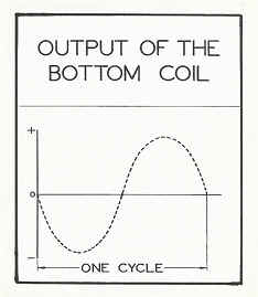
FIGURE 22 B
Now let us consider the bottom coil. Starting with the position as shown in Figure 22A, the current is zero. As the magnet turns, the South Pole of the magnet will approach the bottom winding (Fig. 22B). This will mean that the polarity of the current will be negative and reach maximum when the South Pole is directly opposite the winding. This will be one-quarter of a turn. As the magnet continues the turn, the voltage will again return to zero when one-half turn has been completed. Then the North Pole approaches the bottom winding, so a positive voltage will be produced in the bottom winding. Maximum voltage across this winding will be reached when three-quarters of a turn have been completed. As the magnet completes one turn, the voltage in the bottom winding will again return to zero. It will be noticed that the bottom coil will also produce 115 volts 60 cycle A.C. However, the polarity of each maximum current will be directly opposite that of the output of the top coil.
Since each coil has one wire connected to ground, the two ground wires are connected together at the generator to form a common ground wire. From this it can be seen that from either the top wire or the bottom wire to ground will provide a source of 115 volts 60 cycle A.C.
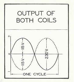
FIGURE 22C
Voltage is determined by the difference in electrical pressure. When the top coil is producing a maximum of positive 115 volts, the bottom coil is producing a maximum of negative 115 volts (Fig. 22C). The difference between the two outside wires then is 230 volts (- 115 volts to + 115 volts).
Summing up the output of the generator, we have three sources of voltage. From either line wire to ground will supply 115 volts 60 cycles A.C., and the voltage from line to line will be 230 volts 60 cycle A.C.
This is the type of current that is supplied to residential districts.
When we compare A.C. to D.C. we notice one other important thing besides the movement of electrons. Since A.C. reverses its current regularly in a wire, we do not say that one terminal of the source is + or - because it is both. However D.C. travels in one direction only so we do say that one terminal is + and the other terminal is -.
We just finished our latest manuals Circuitry and Troubleshooting Volume I and Volume II. They are selling for $75.00 for Volume I and $35.00 for Volume II + $10.00 shipping and handling.
We have a two NEW manuals in their second printing. The first one is titled FUNDAMENTALS OF GAS VOLUME I it is priced at $75.00 a copy + $10.00 shipping and handling. In addition we also have FUNDAMENTALS OF GAS Volume II, which covers “Air for Combustion” and “Venting” it is up to date with the latest changes to the Fuel Gas Code Book. It is also being offered at a price of $75.00 + $10.00 shipping and handling.
The seminar schedule for training at the Gas Training Institute can be found in the HVAC Insider Bulletin Board. The seminars cover:
· Fundamentals of Gas
· Circuitry and Troubleshooting
· Basic Electricity
· Venting
· Hydronic Controls
· Electric Ignition Systems
· Advanced Electric Ignition Systems
· Conversion Burners/Combustion Testing
· Powerpile Systems
If you are interested in information call 401-437-0557 or write to:
Gas Appliance Service Training and Consulting
22 Griffith Drive
Riverside, RI 02915
E-mail gastc@cox.net
###
|